
38×50 Profil Yataklama
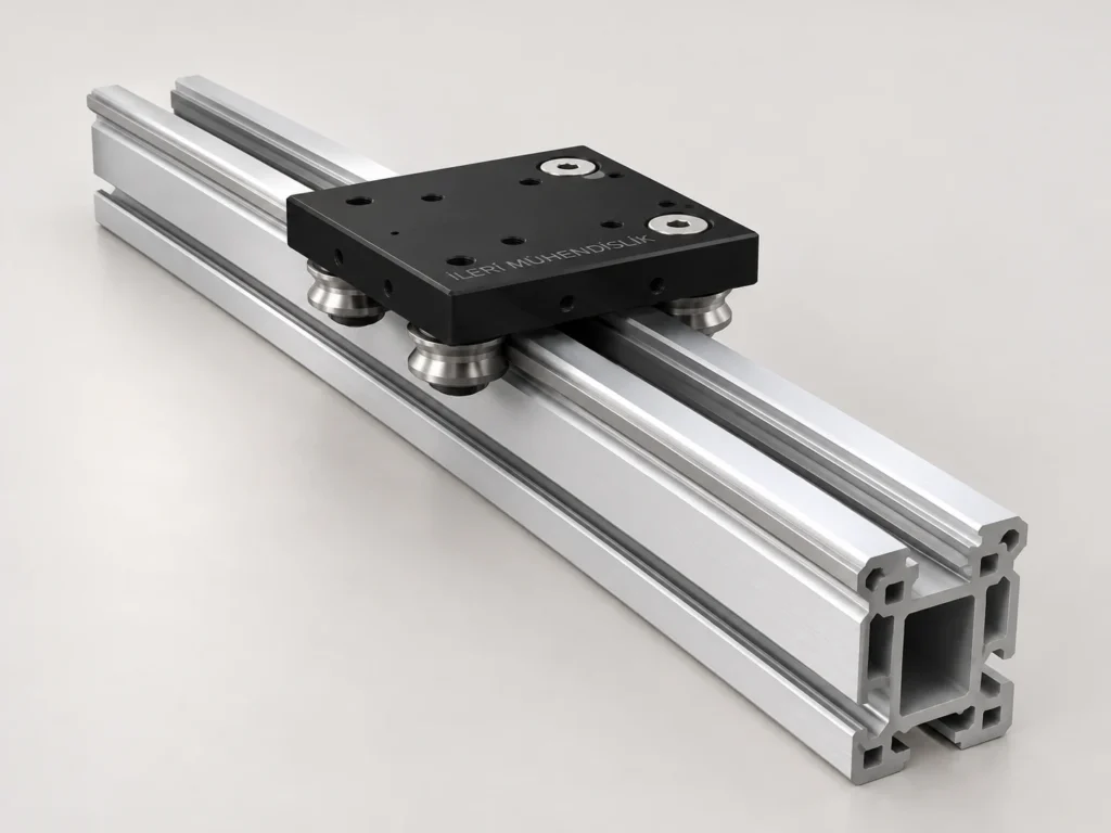
38×50 Profil Yataklama, küçük montaj aparatı ayarı gibi ihtiyaçlarda mekanik yapı ve çalışma koşulları birlikte değerlendirilerek seçilen bir ürün grubudur.
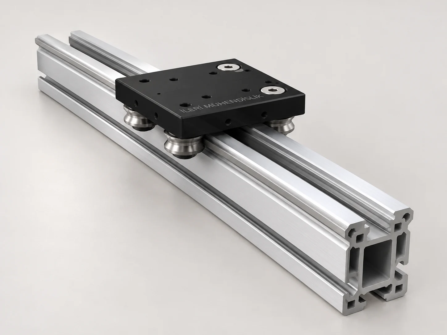
Moving on a small cut profile
38×50 Profil Yataklama, sınırlı hacimde kılavuzlu hareket oluşturmak isteyen tasarımlarda değerlendirilir. Kesit adı ile net taşıma kapasitesi birbirine karıştırılmamalıdır. Özellikle profilin yalnızca uçlardan bağlandığı uzun bir yerleşimde sehim kontrolü gerekir. Rayın altında ilave destek yüzeyleri bulunması, montaj planını değiştirebilir.
38×50 Profil Yataklama — teknik seçim bilgileri
| Group of Products | Manual beding systems |
|---|---|
| The model definition | 38×50 Profil Yataklama |
| Working | Manual/Project External Movement Transfer |
| Source Variant | 38×50 Profil Yataklama Ø6 GCR15 |
| Net Strike | The application is considered |
Table source defines a reference configuration in the catalogue. Visual is a representative work that tells the product group; the connection measurements and final components are verified through technical drawing.
The drive and bed is not the same task.
This mechanical structure guides the moving vehicle in a specific direction. Hand-driven, piston connection or a specific power transfer to the project is a separate design subject. If a drive element is added, the connection force must be determined in advance to which point the car will come. A connection that pushes the direction surfaces to curve, can change the movement resistance and stretching. The product should not be assessed as a motor linear module as it looks like only the external appearance.
Boy, Stroke and Montage Area
The total length of the profile is not the same measure that the car can use. The length of the car, end connections, stopers and desired approach distances limit the work area. It is useful to have a simple drawing that shows the two end locations in your request. Also specify what intervals the profile is connected to the machine and whether there is a constant support below. This information makes it easier to assess the behavior of the body, especially in a long location.
The direction and moment of the load
The transportation assessment uses the distance from the center of the load to the car along with the total mass. A load that is pressed from above, a side-trapped panel and the apparatus on a long arm do not produce the same effect. If there is a blow or sudden position during the movement, this scenario should also be described. Parallelity, load sharing and flexibility of the connected table in the case of joint use of the two bed lines are addressed during technical work. The estimated kilogram capacity from the catalogue group is not removed.
Montage and daily control
Connecting the bed surface to a flat and clean main structure is the starting condition of the proper movement. During the installation the order of compression and connection surfaces are checked. The setting in a variant with the exantric setting is done according to the relevant technical method; the space is not attempted to be removed by giving over-pre-load. The slash, dust and slash can leave traces on the movement surfaces. Before use, the conformity of the connections, end stopers and if there is, the lock must be assessed.
Information to be shared for the offer
Write the full name of the product, the desired profile length, the net strok need and the car unit in separate lines. Show the weight and connection surface of the moving piece. Add additional pieces such as lock, siper or special plate if required to the delivery range. Sharing the measurable crocky with the photos of the two ends of the position in the upgrade of an existing layout allows the understanding of the piece. Final variation, the assembly measurements and working conditions are clarified in the technical interview.
When describing the work
Note how many seconds a movement will be completed and how often it is repeated during the day. The presence in the starting and end positions is not the same as the continuous repetition of the movement throughout the day. Speak the empty and full movements in the circles where a piece is charged and dissolved separately. Remember that the moving load is not only made up of the weight of the piece; the top plate, the apparatus and the connector elements are also included in the account. Showing the access area to be separated for maintenance with the operator's work area in the drawing helps to evaluate the settlement problems that may be met after the installation. If the center of load changes during the strok to be used, also sign the negative position.
Frequently Asked Questions
Can the transportation capacity be determined by the model name?
The load direction, moment, struck, support distances and the chosen variant are assessed together.
What measures are required for the offer?
Note the net strok, total assembly area, moving mass, load center and connection surfaces. If you're choosing a existing piece instead, add the measurable drawing.
Other models in the manual bed systems · All linear movement systems
Technical reference is: Source catalogue information of the product family .
Share your size and working conditions
Let us evaluate the product selection together with the strok, load, assembly direction and quantity information.
WhatsApp üzerinden bilgi alın ↗