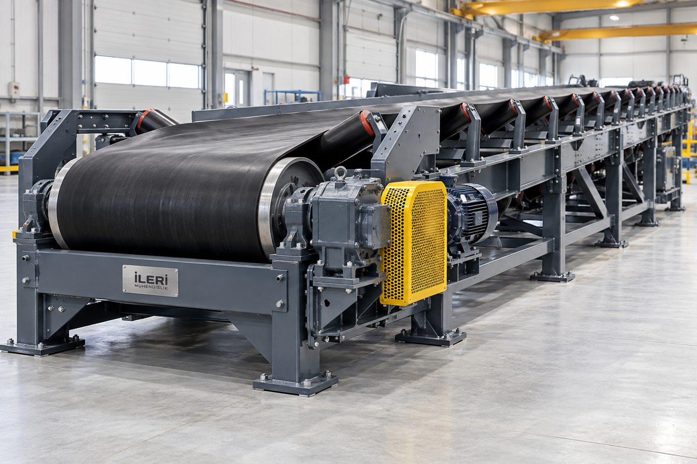
Heavy Load Carrier
The visual gallery of heavy cargo carriers
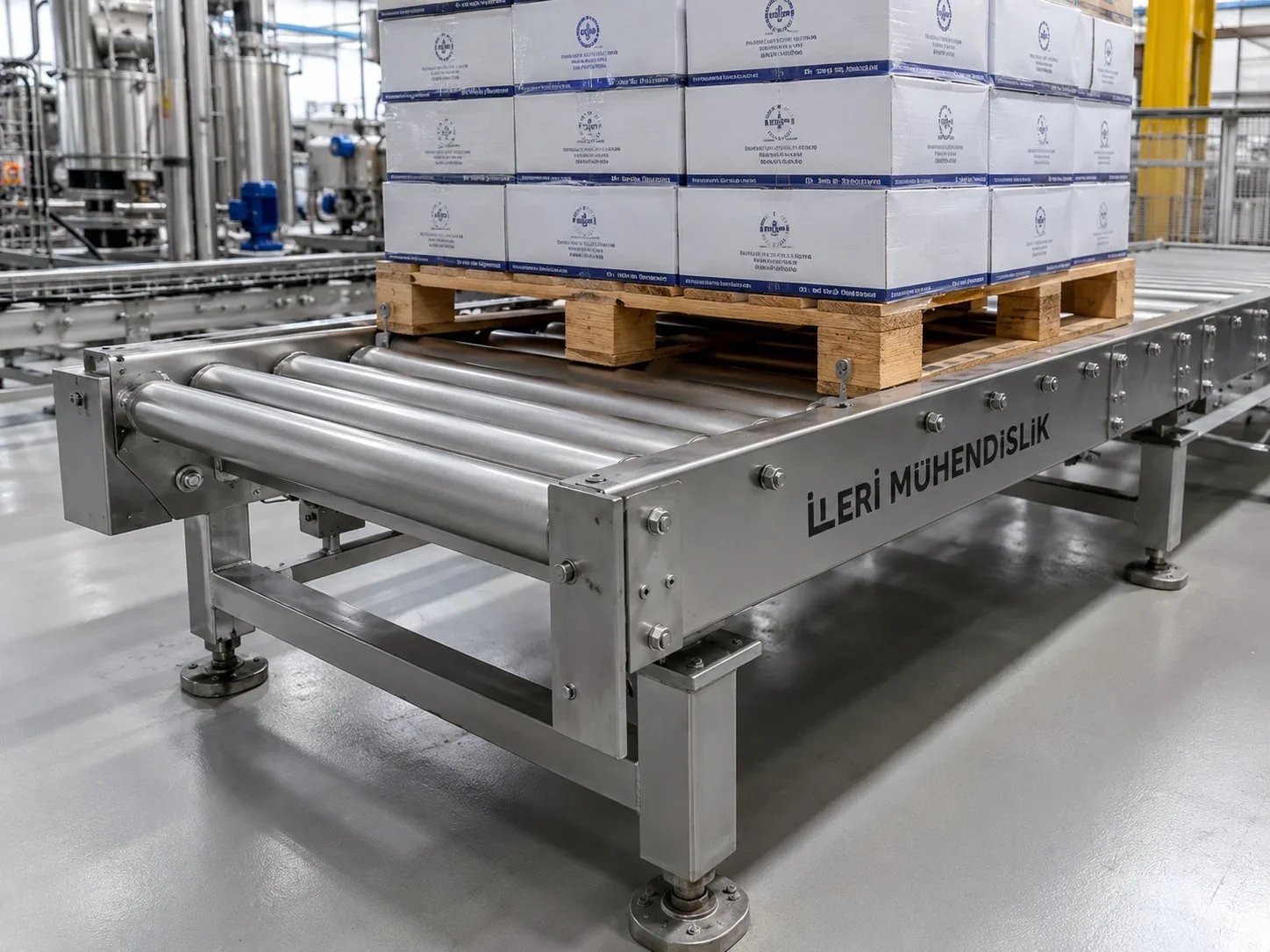
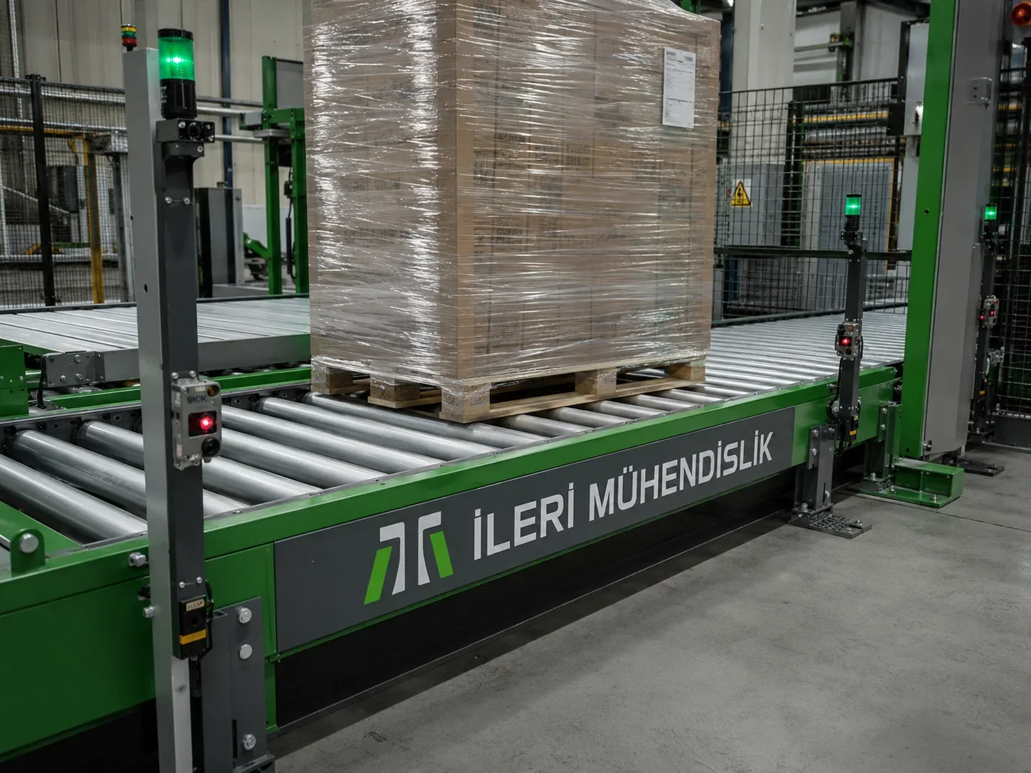
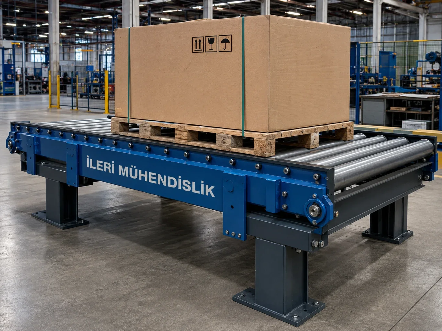
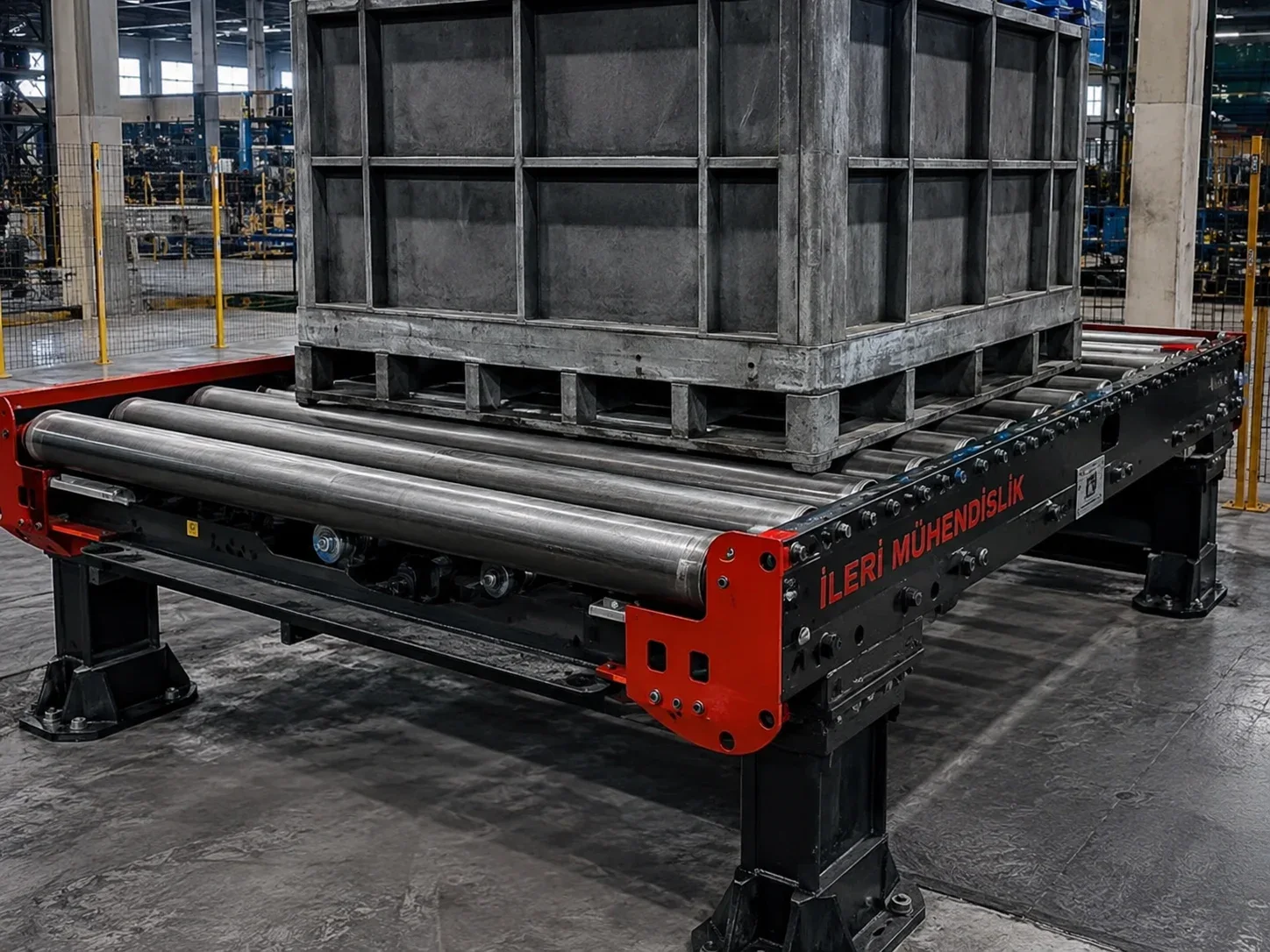
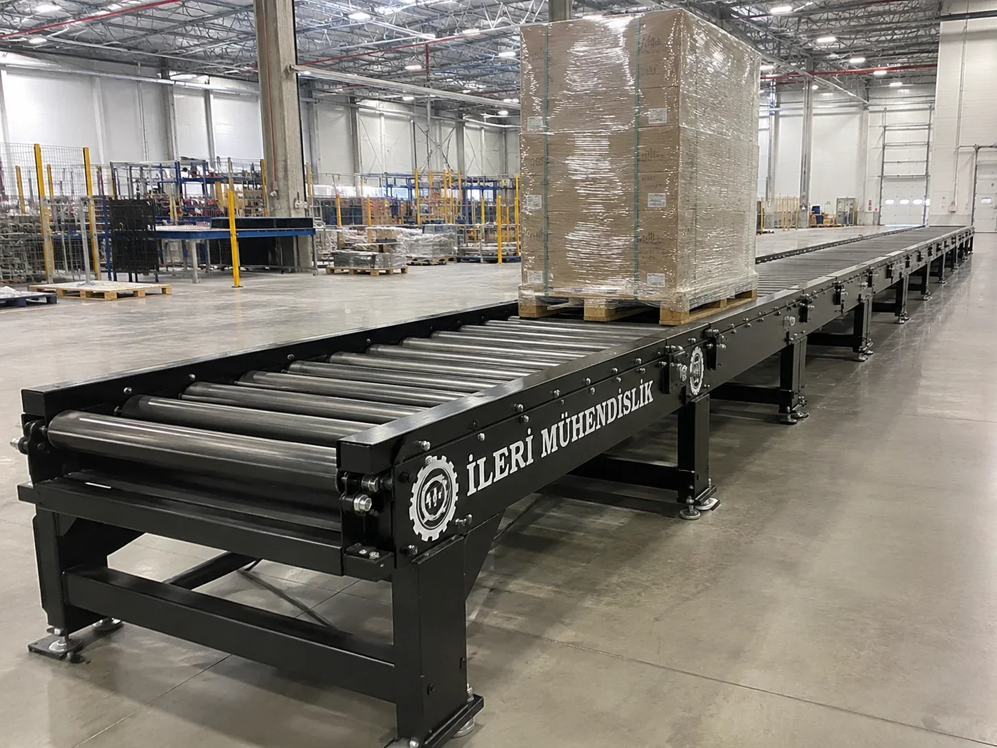
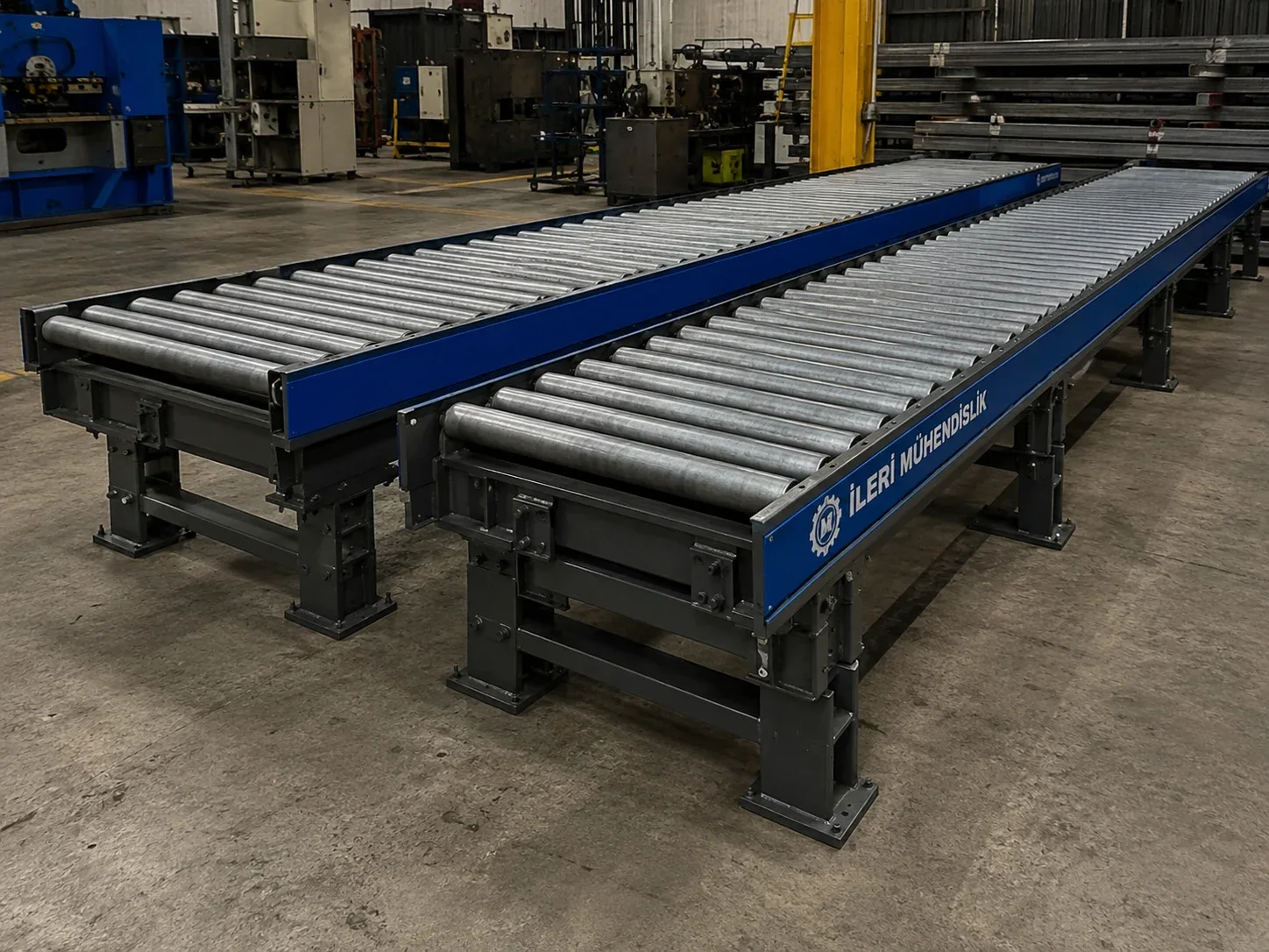
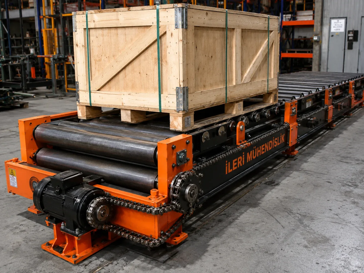
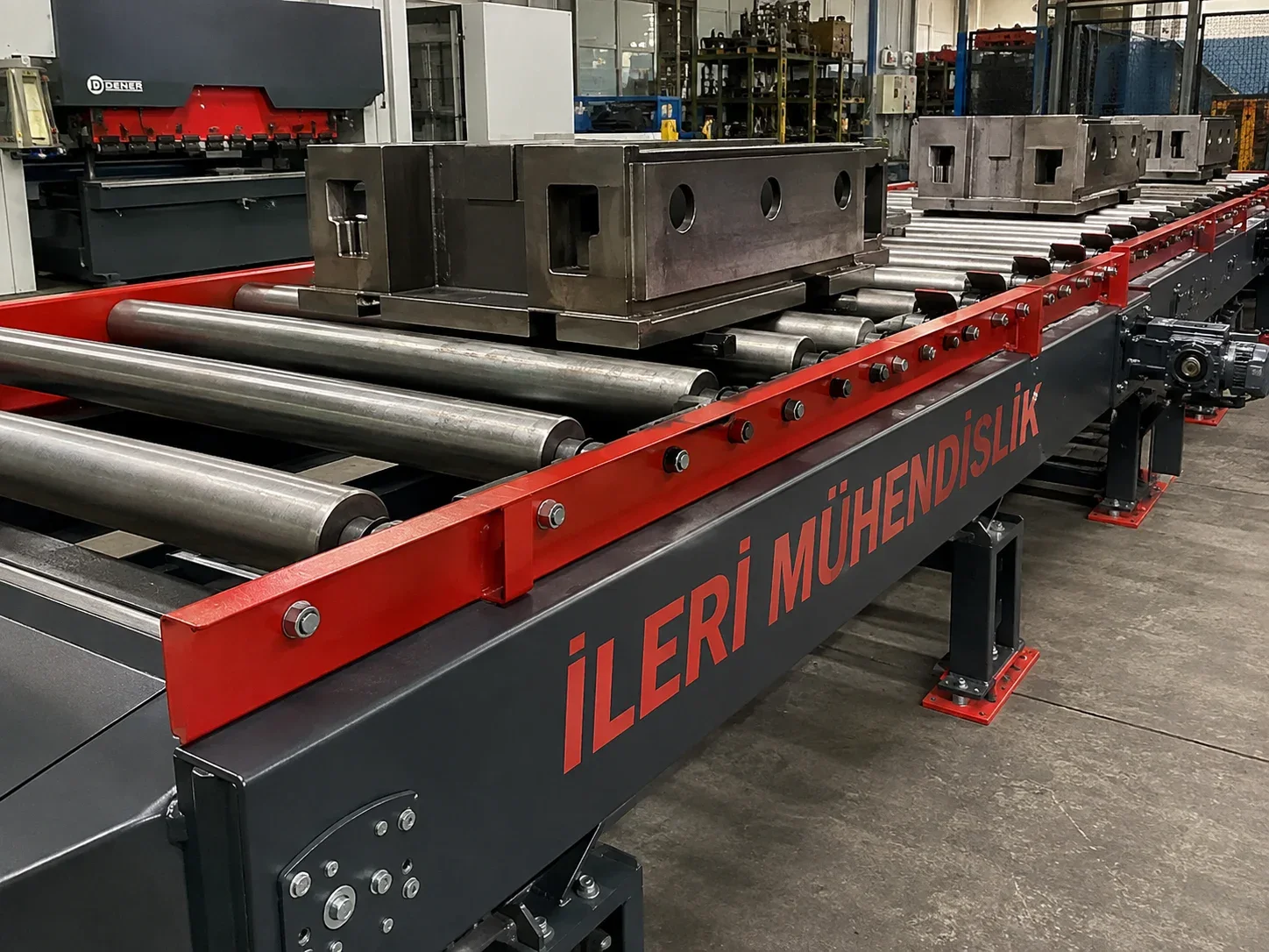
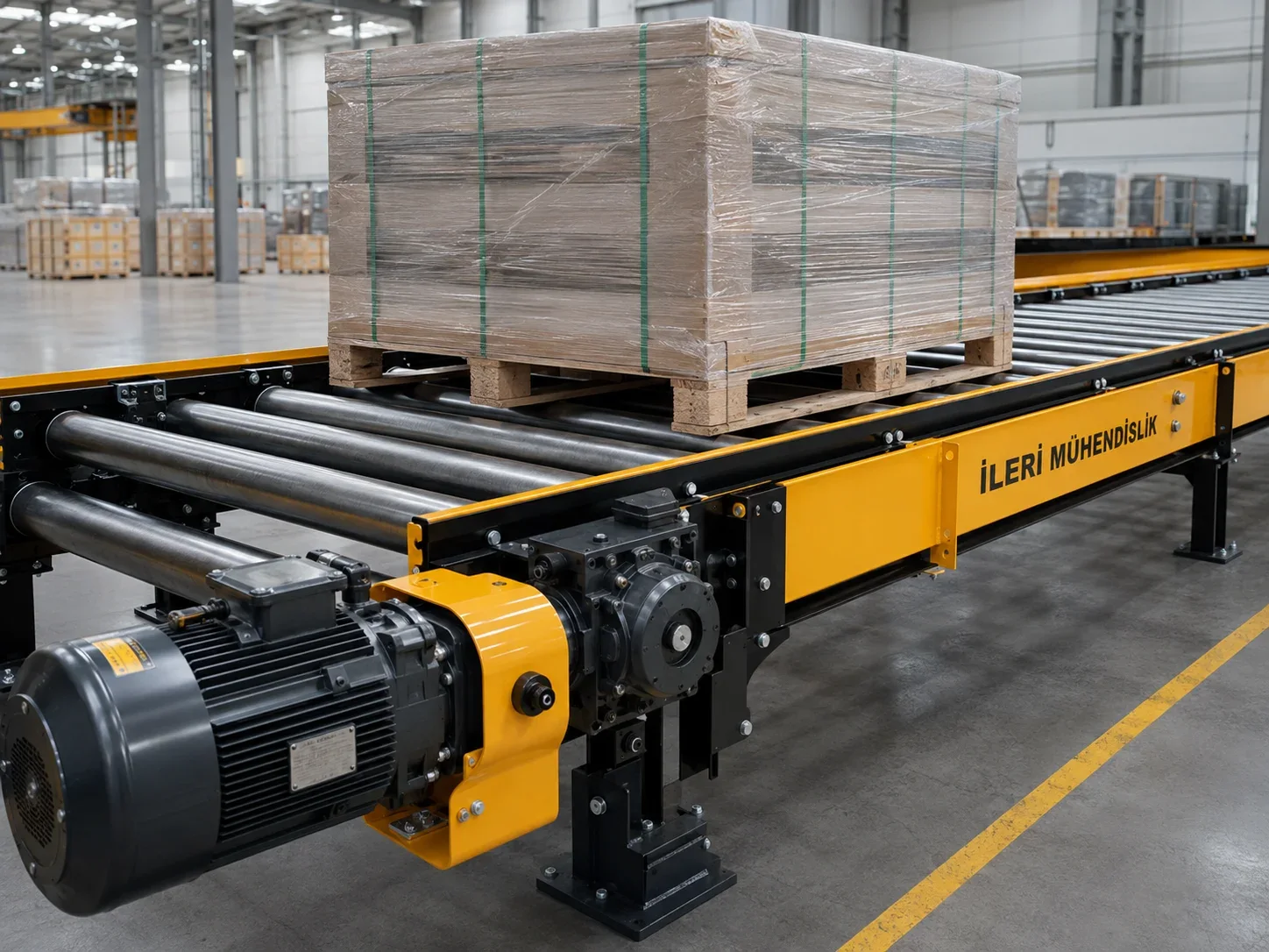
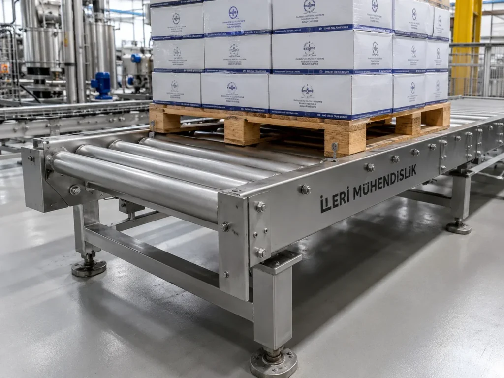
Heavy load carriers are designed to control the transfer of metal parts, patterns, heavy boxes and so on. The choice is not only completed by the knowledge of the weight to be moved; the contact points of the load, the center of weight and even the way of leaving are also required. Advanced Engineering deals with the transfer surface, shade and drawing order by assessing together these working conditions. The goal is to transfer the load in defined support and movement conditions from entrance to exit.
How to assess capacity for heavy load carriers?
The total weight of a metal piece that is multi-foot with a wide-based box may be the same. But the local forces transferred to the carrier elements are different. The load is pushed to which rounds or band areas, the study is done whether this contact has changed during the transportation. The real base geometry should be based on the design without assuming that the load is equally distributed to every point.
The total load that will be on the carrier at the same time with the unit product weight is separate information. The waiting of a more heavy product creates different conditions than the transport of a single product for the shase and drive. The length of the load, the width and the height of the weight center according to the base should also be indicated. The movements that may occur during the direction change and position in unbalanced loads are also assessed.
Installation and support arrangement
The impact that occurs during the leaving of the load to the carrier with a wire or forklift may differ from the normal transport load. The method of charging, the leaving height and the positioning sensitivity of the operator are therefore important. The rolls, the carrier surface and supports in the entrance section are treated according to these conditions. If the carrier is known to be used in a working form to get a blow, it must be clearly shared in the offer phase.
The support opening and foot placement of the shell is assessed along with the load’s position. The location of the product at different points on a long line may not create the same difficulty. The ground connection, the current laying conditions and the incrusting possibility should be considered in the installation plan. Choosing a powerful engine does not replace the inadequate carrier body or the inappropriate ground.
Rule, band and drive selection
The choice of the transport surface depends on the base structure of the load. In the rolled order the roll range, the tube diameter, the miles and the rollers are handled together. In the banded order the band structure, the support surface and the tambours are selected according to the load conditions. The impact of sharp edge or hot parts on the surface should also be assessed. If necessary, the transfer of the product on a suitable carrier instead of direct contact is considered.
The first output conditions as much as the load in motion in the drive account are also important. The number of stops, the desired speed, the transfer method and mechanical resistance are assessed together. The connections and control mode on the shifted lines must be in accordance with this way of work. The engine, the reducer and the transfer elements should not be considered as parts to be selected independently.
Control position and load position
The product should be prevented from moving or losing balance during the stop of a heavy load. The standing form, speed and the base holding of the load are handled together. The impact on the movement of the load is also taken into account if mechanical stop is needed. The desired location, repeatability and how the product will be taken to the next processing should be indicated as the design data when delivered to a sensitive station.
If there is waiting or storage on the line, it may require independent areas and product detection arrangement. It is defined in the work scenario how the load will be kept in the connection machine failure or energy cuts. Reworking should take place in conditions where the operator can see the load position and the system is ready. Control design should follow the same load flow as the mechanical transport arrangement.
Care and work area
The turn of the rolls, the sound and heating in the beds, the stretching of the drive parts and the shase connections are regularly controlled. Small equalization errors in systems operating under high forces may turn into more noticeable problems over time. Access to the area and lifting equipment where the load can be taken safely for maintenance should be considered. Moving transfer areas should be protected, energy and cargo resources should be put into safe state during intervention.
Prepare for the price of heavy cargo carrier
The maximum unit load, total line load, product base drawing, weight center and load method for the offer must be shared. Line measurements, speed, work circle, environment and standpoint are other basic information. Shase structure, transport surface, drive and automation range determines the price. The establishment drawing that shows the ground and connectivity points for existing systems to be installed facilitates the assessment of the ground and connectivity points for the existing facility.
Frequently Asked Questions
Is the power of the engine understandable? No. The shade, the carrier surface, the rolls, the connections and the load distribution must be appropriate together. Motor power is only part of this assessment.
Can different weight products be the same or even carried? The support and detection conditions of the smallest product should also be checked as the load conditions of the heavest product.
Can the current carrier be increased? Capacity increase without examining the shade, ground, rolls and drive as a whole is not accepted. The scope of the variation is determined by the existing measurements and working conditions.
The existing product information
| The product | Heavy Load Carrier |
| The basic function | High unit load according to projected six and mounting transfer |
| Area of Application | Metal pieces, shapes and heavy box transportation |
| Information needed in the election | Load center, impact, support intervals |
| Technical control point | Capacity cannot be determined by motor power alone. |
Ask about this product or application
Product images