
Triger Track Track Movement Systems
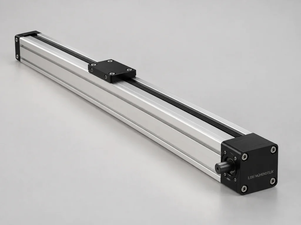
Triger thread is product groups that make linear movement with modules, thread and shell order. Guidelines can be provided through the rail or shell structure. In this section you can study the Compact, Sigma and Linear series separately; you can compare the model, thread and connection differences of each group.
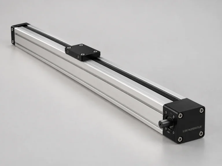
The compact series
The compact series has trail and guidance information, strok selection, assembly recommendations and technical assessment. Share your application with Advanced Engineering.
İncele →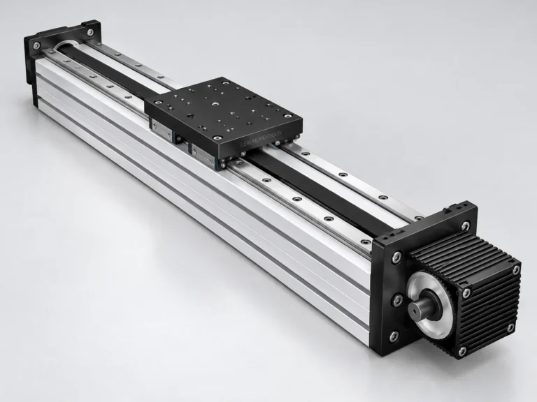
Linear series
Linear Series with trail and guidance information, strok selection, assembly recommendations and technical assessment. Share your application with Advanced Engineering.
İncele →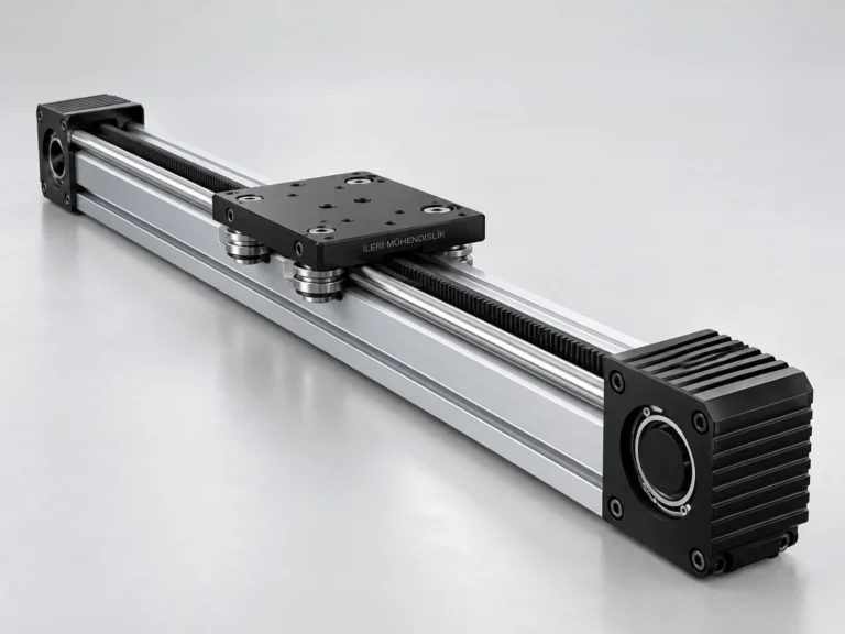
The Sigma Series
The trail and guidance information for the Sigma Series, the selection of strok, the assembly recommendations and technical assessment. Share your application with Advanced Engineering.
İncele →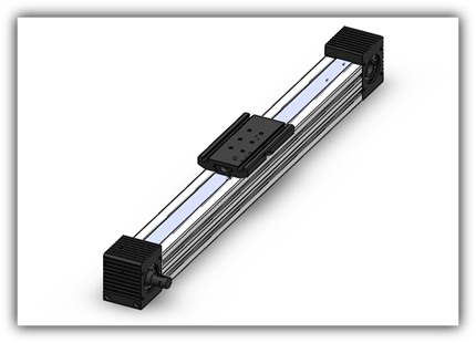
60*60 Compackt Module
60*60 Compackt Module examines the rotating areas of the thread and the movement of the carrier within the same settlement. If used in the narrow machine area, the engine output and the...
İncele →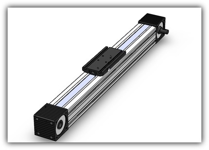
80*80 Compackt Module
80*80 Compackt Module option is the installation to the body and the equipment connection to the carrier is treated as two separate surfaces.
İncele →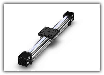
45*90 Tiger Tiger Module
45*90 Cocktail Triger Tahrikli Module is provided through the guidelines. if the carrier carries a load away from the axis, the connection geometry and the...
İncele →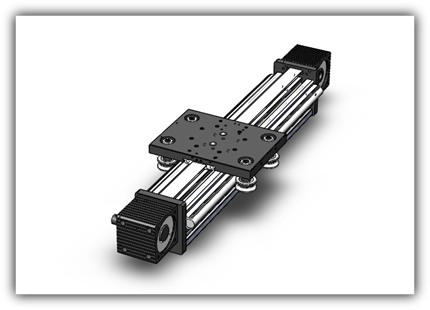
90*90 Tiger Tiger Module
90*90 Makaralı Triger Tahrikli Modül için tabloda verilen kayış ve kasnak bilgileri aynı ürün kaydının parçalarıdır. Şaseye bağlantı noktaları,…
İncele →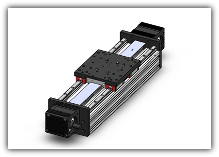
90*180 Tiger Tahrik Module
90*180 Tiger Tahrikli Module is the width body Tahrikli guiding option. The installation of the equipment to be connected to it, the body size and the specified...
İncele →How to evaluate the trail?
The trigger thread transmits the movement between the shells to the linear carrier. This task is different from the guidance of the load. The rail or the coated bed carrier produces the shell movement while determining the direction of the carrier. The fact that a system is shelled alone does not explain the speed, capacity or positioning accuracy. The line definition, shell layout, moving mass and work circle should be evaluated together. The engine and driver may be separate delivery pen from the body; it is clearly indicated in the proposal that the cover of parts such as the connection flame and caplin is included.
The total length and length of the assembly
The length of the module from the outside to the outer with net strok is not the same measurement. The end drive group, the length of the car or plate and the approach parts affect the settlement. A measurable drawing that shows the starting and end position is more explicit than the total profile length is written only. Also specify the area allocated for moving cables, tubes and side connections. The area that needs to be left empty in the surrounding depending on the movement of the body or plate may vary. The desired strok is verified along with the final mechanical structure.
Load center, speed and circulation
The moving weight includes not only the moving pieces, but also the top table, the apparatus and the connective elements. The distance from the axis surface of this mass changes the moment effect. The speed target should also explain the acceleration, slowing and waiting times. The same carrier is not the same working condition to make continuous rotation throughout the day with a interim setting. The speed in the reference table is not a general guarantee for all loads and stakes. The drive, guidance and control system are selected together through the application.
Installation, maintenance and environmental conditions
The flatness and rigidity of the main structure to which the body is connected is important in the assessment of the movement. The assembly errors are not attempted to be fixed by just stretching the tape more. The back and guide settings should be done according to the technical method of the relevant product. If there is a dust, dust, moisture or liquid contact, add them to the demand. The appearance of a closed external body alone is not a statement of a specific protection class. The leaving the access area for the shifting, maintenance and, if necessary, shifting is part of the settlement.
What information is needed for the offer?
Share the model name, unit, net strok, load, working direction and approximately speed target together. It is useful to add the drawing that shows the connective holes of the upper plate and the center of the load. If there are more axes, specify which axes carry the other. In the renewal of a existing system, the line definition, the engine connection and external heights are also compared. If you need automatic signal exchange or sensor, write them into the delivery range. The final brand, variance and installation measurements are clarified in the proposal by technical conversation.
Planning the area of movement together.
The load and discharge positions of the product should be drawn together with the fixed machine parts around it. It is not enough that a device is fit only in the starting position; the external contour is controlled throughout the strok. The operator's work area, the direction where maintenance covers will be opened and the turn area of the cable carrier are also considered. If the use of the vertical axis is planned, the load holding when the energy is cut is also designed. It is unassured that the thread drive is a safe load lock itself. These details allow the mechanical product selection not to be separated from the whole machine.
Comparing more than one model
Comparing the same load, strok and assembly direction makes you see the tasks of different products more clearly. Write which link sheet, the thread and the guide element is assessed next to the model name. Showing the most negative position of the load on the drawing is more explicit than just reporting the total weight. If there are waiting times in the starting and end positions, add to the circle description. Instead of indicating the measures that are not yet cleared in the offer, also mark the exact value. In the technical interview these points are verified together and the delivery scope is determined according to the whole application.
When completing the request list
If more modules are required for the same machine, write the task of each axis separately. Do not combine the axis that are different in one line. If the product has empty and full movements, separate them in the circle description. In the order that one module carries the other, the weight of the upper axis itself also enters the sub-axis assessment. Also mark the unmeasured connectivity places in the drawing. This information helps prevent the wrong part from being selected only by the name similarity and the offer scope is understandable.
Share your Strok and Application Information
Let’s evaluate the thread, guidance, assembly and drive range together.
WhatsApp üzerinden bilgi alın ↗