
The turn tables
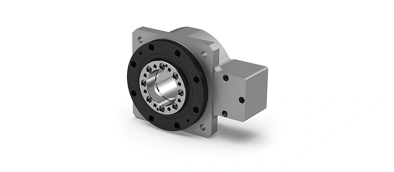
Ürün modellerini inceleyin
Ürün görseline veya adına tıklayarak ilgili serinin teknik bilgilerine ulaşın.
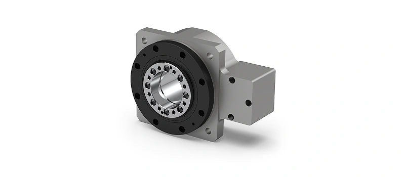
Turn tables — product options, technical tables and application-based selection information.
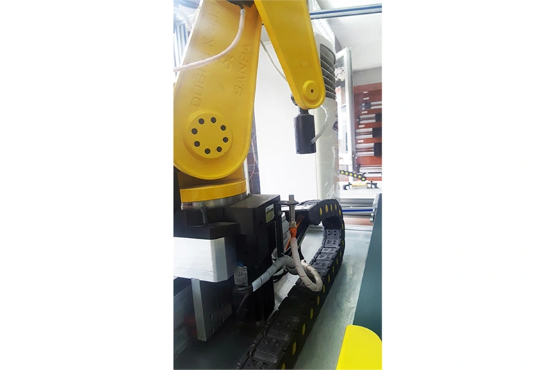
The rotating tables are assessed in the machine axes that a work piece or fixture must be moved to a specified angle. In this section, the NT60, NT85, NT130 and NT230 models are presented along with the measurements in the source catalogue. Servo-driven structure can be studied in orders that require angle movement such as filling and assembly stations. The geometry of the load to be connected with the table size should be taken into account when choosing.
The difference between the model and ratio of the NT series
The source catalogue indicates the ratio of i:10 for NT60, i:30 for NT85, i:10 for NT130 and NT230. These ratioes are not mixed with the engine side and the output movement are assessed together. It is unpredictable that the number in the model name is equal to each drawing size. For example, the measurements of the body, the turn surface and the assembly holes are included in separate columns. The layout of the hole should not be drawn according to the model name only when the installation is prepared.
The position of the load and the movement of the movement
The distance of the load from the center is as important as the total load transferred on the table. Fixture, work part and connective elements are handled together. It should be indicated how long the movement will be completed, how much it will be expected in the position and how often the circle will be repeated. The same mass is located in a different semiconductor may require a different assessment for motor and mechanical transfer.
The load column published in the table is protected by the kgf unit. This value is a power unit; it should not be interpreted as a general use approval alone for different load aspects and working conditions. The engine column shows the power information provided in the source. This information does not mean that the engine is included in each delivery package; the engine, driver, cable and mechanical connection scope is also specified in the proposal.
Technical drawing and connection control
A, B, C, W, H, H1, L, D, D1, D2, d and M symbols must be read along with the original drawing. The rear hole settings of the surface where the body connection surface and the work piece are connected are different. The single page of the source document of this product can be opened through the local PDF link. The catalog page is not re-drawn, the original size labels are preserved.
In a new machine design, the area covered by the engine, the cable output and maintenance access should be scheduled early. the fixing or conservation around the table should not prevent the movement path. If the existing machine is renewed, the connection intervals of the old body and the direction of the engine side are measured. The similar external appearance does not prove that a different table can be directly replaced.
Information needed for the offer
In the offer request, share the target model, the angle to be turned, the time of movement and the image of the load settlement. specify whether the turn is constant or between specific angles. Zero position, detection need and the communication of the control system with the engine are also assessed. Just reporting the table diameter does not complete the entire selection of the servo axis.
Not to install and install
Connector surfaces must be clean and prepared according to design. Installation error should not be tried to be removed by forceing the cuts. In the first trial, mechanical spots and cable movement around are controlled. Detection of the fixation and part should be assessed so that the place during movement will not change. The manufacturer's installation and maintenance instructions are based on the technical documentation of the selected model.
Interested drives and guidelines
to check the engine side. Servo Motor and Drivers for other transfer solutions. The Reducers You can go to the section. in the order that the linear movement of the same time needs Linear Movement Systems These products do not perform the same function; they are selected together according to the machine's axis location.
Frequently Asked Questions
Does the number in the NT model give all the assembly dimensions?
No. The hole centers, the body’s outer size and the rotating surface are separate measurements. Local technical drawing and model table should be studied together.
Does engine power information mean ready servo package?
The engine column is the matching information in the source catalogue. The actual delivery range, the driver and the connector elements are also defined on the offer.
clarification of order
After the product selection, the unit, delivery scope and if there is a special processing need must be explained in writing. It is unpredictable that the engine, cable, connector or other component shown together in the visual is included in each package. The label and connector measures of the delivered piece are compared to the approved definition before the installation begins. If the difference is seen, the installation is not attempted to be adapted by forcing the installation; the piece information is shared for technical assessment.