
Conveyor Cards and Side Guides
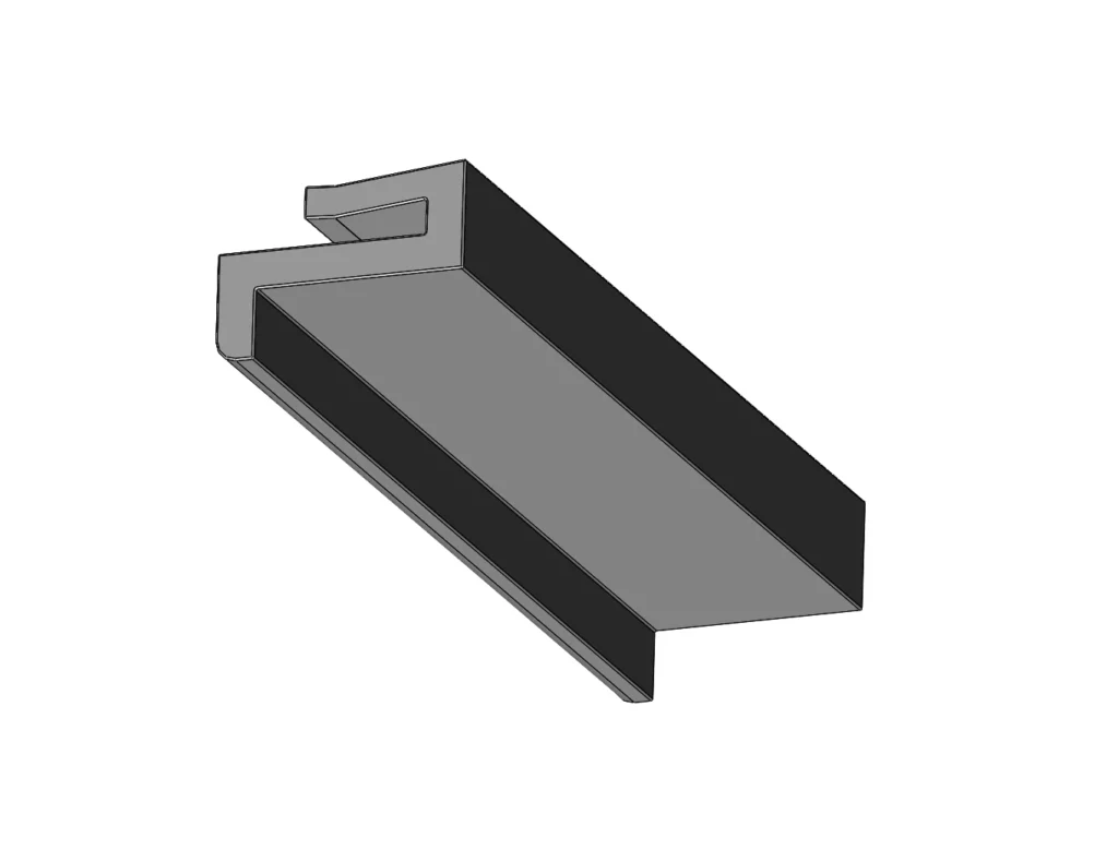
Compare the shell and side guide profiles with their own shell appearances. Each profile is displayed on a separate product page.
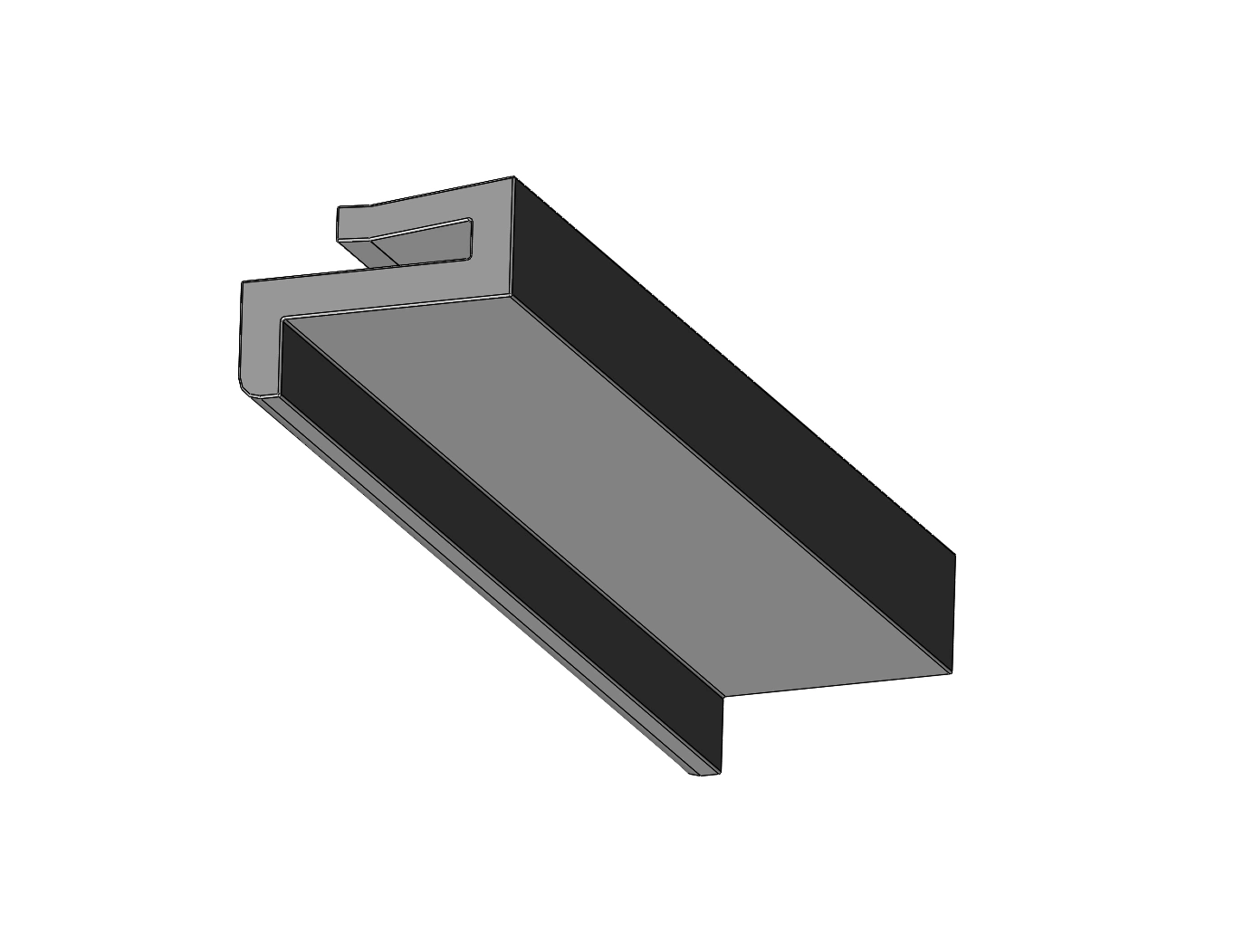
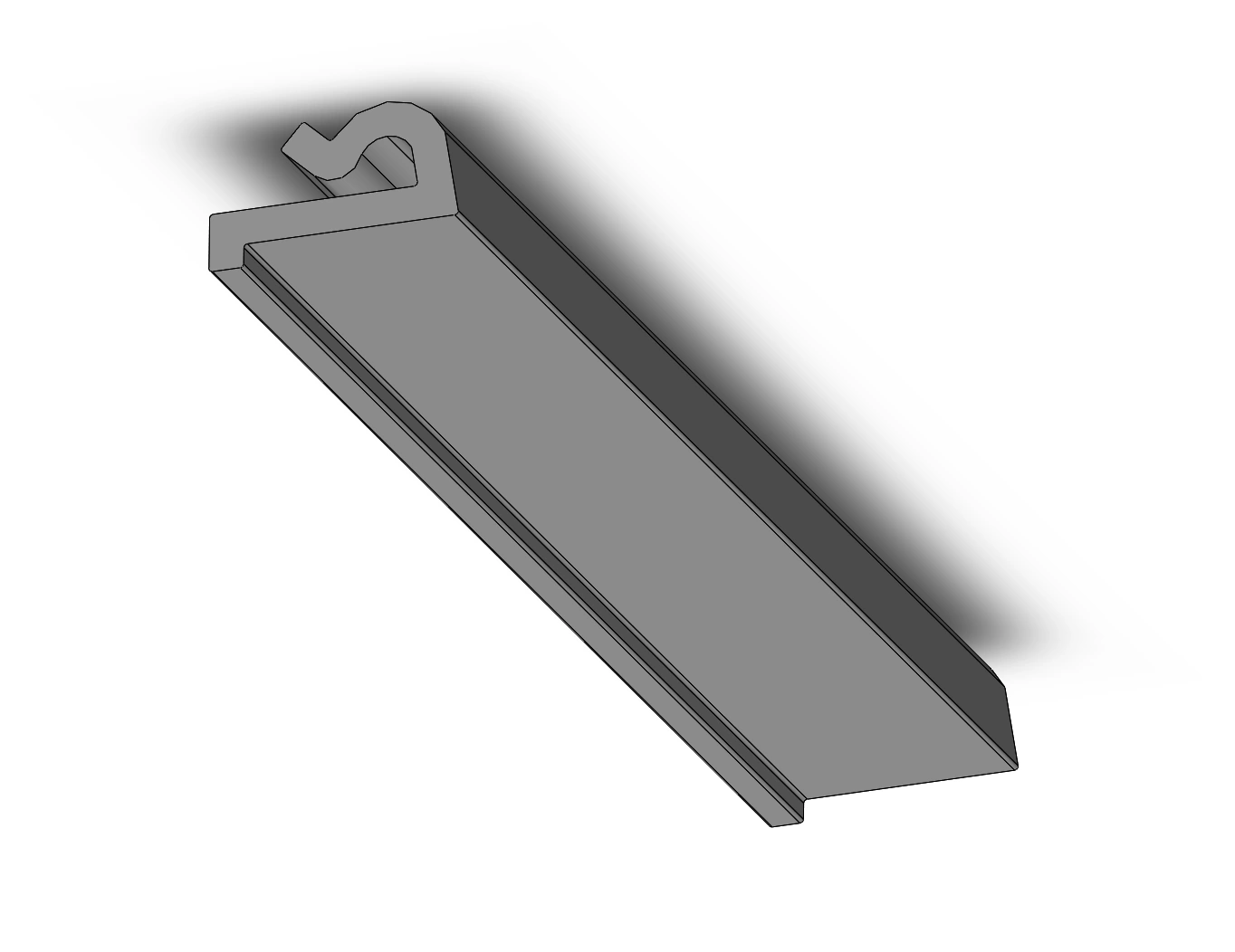
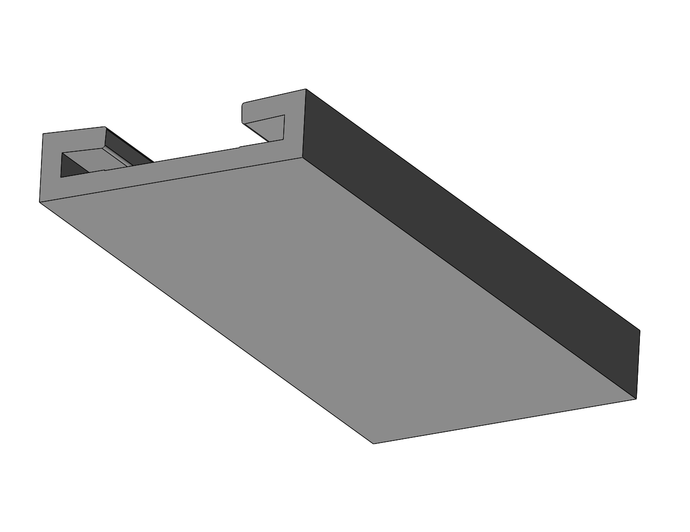
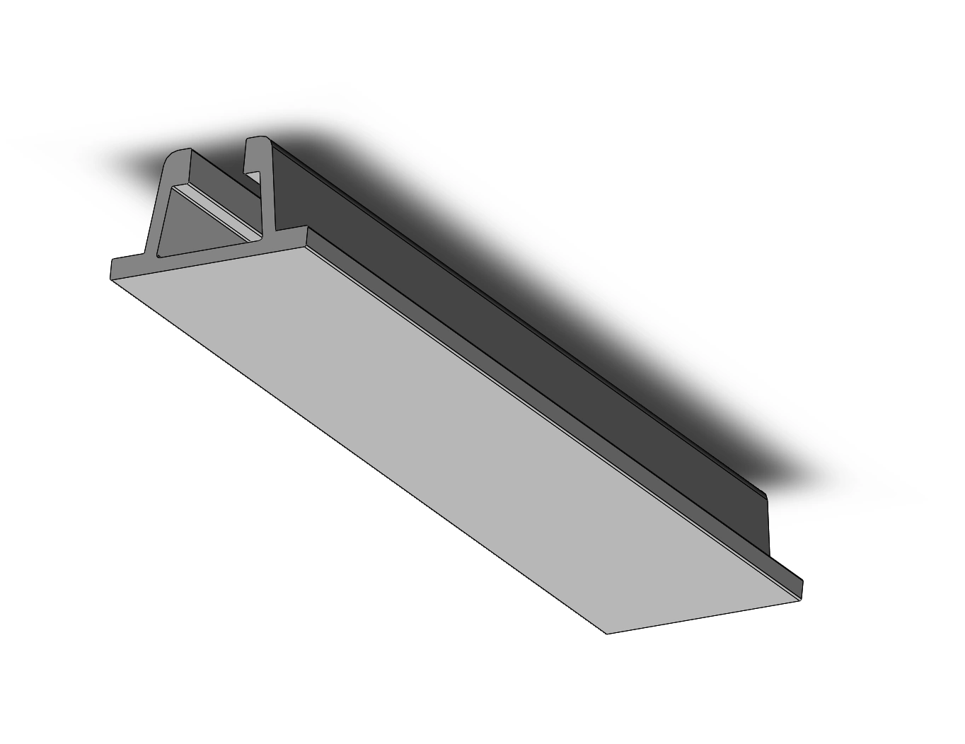
The points to be noticed when choosing carrier and side guides
The surface width is not enough in the selection of the profile. The nails sitting on the carrier part of the cut, the channel structure and the connection form of the opposite part are controlled together. The two cut appearing in the same external width can be placed on a different profile or a different sack edge. Therefore, the cut drawing is the main reference of the assembly.
The surface to which the product is contacted in the side guide, the product's rotation behavior and the clarity between the band are assessed together. The side barrier and the shell do not see the same function. The measurement of a profile that is not published in the shell is not removed from the photo; the shell image and sample information of the existing piece must be shared.
Technical image and model comparison
You can click on the product card to move to the separate page of the family you choose. The technical drawing is not used for the same purpose as the product appearance. It helps to understand the structure of the visual piece; the measurable appearance is based on connection and assembly. When multiple variants are displayed on the same technical page, match the Advanced stock code in the drawing title and in the technical table.
The empty cells in the table are not filled with predictions. the measurement unit is unknown or the record that is unconform in the catalogue is described on the product page. a non-published size is not calculated by the pixel ratio of the photo. the ordered piece must be checked that the definition written on the offer is the same as the model code. Even if the family name is similar, the link layout may change.
Measurement and offer information
In your request, specify the stock code, quantity and use place of the product. If you want to change the existing piece, share a picture of both the general appearance and the connectivity points. Breadth and infinite environment length for the band; cutting and size for the profile; number of cables and movement distance for the cable channel should also be ⁇ . Explain whether a single piece or a set with its connectivity is required.
After the technical comparison is completed, the delivery scope, material, color and necessary processing details are clarified on the offer. It is unpredictable that a link piece shown in the photo is included in the delivery. The delivery scope in the source is clearly written in models that this information is found on their own product page. Uncertain accessories are considered as separate pen before ordering.
Installation and control
The surface, the direction of movement and the access to maintenance before installation are checked. Only the renewal of the piece without the cause of the failure in the old product can cause the repetition of the same problem. Application details such as the swelling in the wire, the direction gap in the band or the excess availability in the cable channel should be shared in the technical assessment. The choice of product is based on the own installation instructions.
Frequently Asked Questions
What code should I use for the offer?
Use the IM code shown on the product page. This code is Advanced Engineering stock definition; it does not replace the manufacturer name or conformity certificate.
Can I use the size in the image directly?
Use the values in the measurable drawing of your own model only. Technical data for a lack of field From the contact page Ask for a picture.
Profile and portfolio link
The cutting of the existing metal carrier to correctly select the rubber profile should also be known. Even if the upper contact surface seems appropriate, it may not sit on the opposite piece of the lower nail or channel. Therefore, it is useful to share the upper, bottom and side appearances of the cutting together instead of just writing the width when taking the measurement. The presence of the cetvel next to the photo helps to pre-evaluate; the technical picture or sample for the exact assembly measurement is based.
The use of the profile on the straight line may not require the same assembly in the turn section. The opennesses in the passing places, fixing points and movements occurring during work should be assessed. If the length is cut, the total size and the piece is specified separately. The additional places of the line consisting of several pieces are also controlled in order to ensure that the product does not form unwanted stages on the contact surface.
In the side barrier application, the guide height is considered along with the weight center and contact point of the carried product. The console or connection part of the profile itself carrying it with it are different products. The appearances together in the photo do not show that they are included in the same delivery pen. The profile length, the number of connection elements and the special end processes should be written separately during the preparation of the offer.
How to specify a special connection?
Describe the desired change in the measurable picture. Report the connective surfaces of the opposite piece and the delivery length separately. The special processing request must be clearly written on the offer. It should not be assumed that a standard appearing detail is included in the delivery.