
The induction of chromium covered Miller
Ürün modellerini inceleyin
Ürün görseline veya adına tıklayarak ilgili serinin teknik bilgilerine ulaşın.
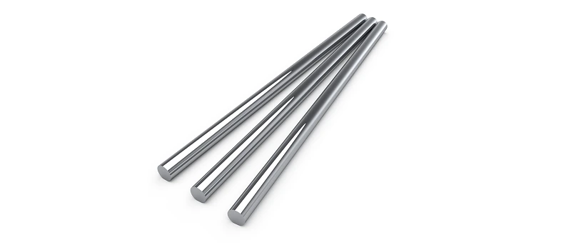
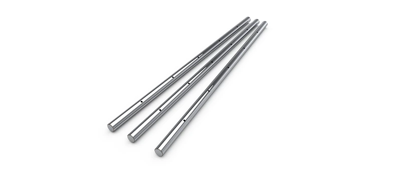
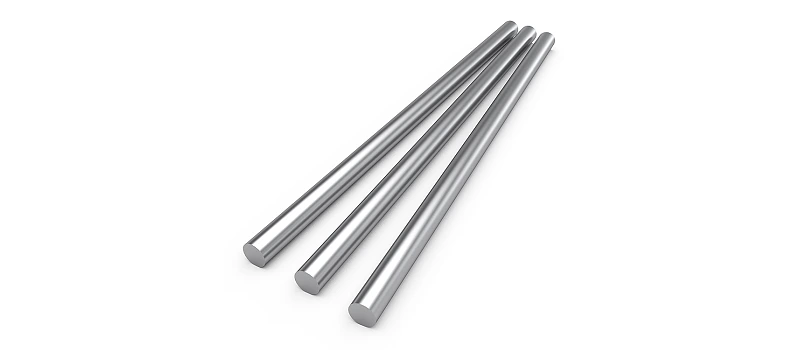
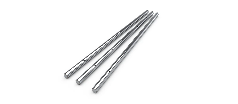
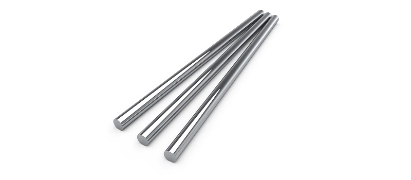
Check out the product families for Induction Chromium Covered Miller, published measurement tables and source technical images.
Basic information in the selection of induced chromium-covered Miller
The induced chromium-covered miller creates a cylindrical guide surface along with the appropriate linear rollers. This group has full and hole options under the materials titles of CF53 and GCR15. The material name does not define all mechanical characteristics of the millin alone. The product family, diameter and assembly requirements indicated in the source are assessed together.
Even if the miles filled with a hole mile are in the same external diameter, the cutting structures are different. This difference is important in terms of weight, the internal transition area and the mechanical behavior of the design. If a connection is planned to be processed to the hole body, the thickness of the meat and the end connection are also studied. The hardness, the thickness of the cover or the tolerance value not included in the source table is not attributed to the whole product as a general assumption.
The cleansing of the working surface and matching it with the rolling is important for proper movement. The distance between the freelance and support points is not assessed, and the result is not made about the behavior of the shrimp only through the diameter. In a two parallel miles used order, the body equation and bed placement are controlled together; the assembly error is not attempted to be fixed by excessive pressing.
The total size, work length and end processing needs should be written separately in the mile order. If the receiver needs a female, segment channel, cave or special hole, a measurable drawing is shared. Cuted surfaces should not be depleted by the manual surface that works during the movement and storage. If a surface feature is not required in the technical table, the acceptance requirement will also be defined in the offer stage.
How to use technical tables?
The separate subpages of the products contain models and measurements published in the source. By clicking on a product card you can examine the images, technical drawings and tables on the separate page of that family. In different families the same letter can define a different size; therefore the symbols in the table must be read along with their own drawings. The fields left empty in the source have not been completed, a measure that is not in the drawings has not been re-produced. If the unit information is not clear, it must be verified by the manufacturer's drawings.
The tables are for technical comparison; it is not an instant stock or delivery time statement. the connection arrangement and working conditions of the products that appear in the same nominal dimension may be different. It is not necessary to make a piece change through a single number or a photo similarity only. The application requirements are compared with the full model definition. If a difference is seen in the source data, the relevant line is also checked before ordering.
Measurement and offer information
When you request the offer, share the full code of the product, the details of the item and the photo of the existing piece. Add a measurable drawing if you need a specific processing, different materials or a specific delivery range. It should be clearly stated whether a product is required as a set or as a single component. If more than one piece changes in the same machine, the connected surfaces and matching parts are assessed together.
Before installation, the connective surfaces, the working direction and the maintenance access are reviewed. The cause of the failure in the old piece may not solve the problem of the new product, the problem of the installation, the balance or the pollution without understanding. The manufacturer's installation, lubrication and use instructions are based on the selected product. The general selection description here does not replace the technical documentation of the full model. The measurement verification and application assessment ensure the proposal is openly prepared.
Interested Products Groups
To check the machine's guidelines and drive parts together Linear rail and cars , Mills and Summons and The machine spare parts You can switch between. The product selection is done taking into account the entire installation of the machine, because the tasks of the connected parts are separate. You can request evaluation by sharing your technical picture with Advanced Engineering.
clarification of order
The display of an accessory with the main product does not mean that it is inside each package. Combination components, such as connector boards, intermittent parts, rollers or engines should be specified separately on the request. When the product is delivered, the measurement draw is compared to the definition of the piece; a difference seen before the assembly is transmitted to the technical assessment. Thus, the assembly repetitions may occur due to the missing component or the wrong assembly are reduced.
Frequently Asked Questions
Is only a photo enough for the induced chromium-covered Miller?
Photography is useful to recognize the family; for the exact choice, it requires model code, connection measurements and working conditions. The images taken from different aspects of the current piece are assessed along with the measurement technical drawing.
Are all the products on the table ready stock?
This section shows the technical product scope. Current stock, delivery time, special processing and item information are verified when the offer is prepared. Listing a technical line does not mean that a particular piece will be delivered immediately.