
2.2 kW Converter Speed Control
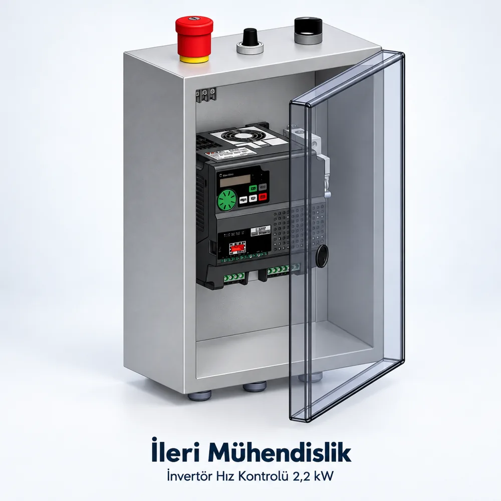
2.2 kW Converter Speed Control is an option that is evaluated along with the project’s measurement and installation needs in the speed control product group. Advanced Engineering deals with your choice along with the technical options of the product and the conditions of the structure to be used.
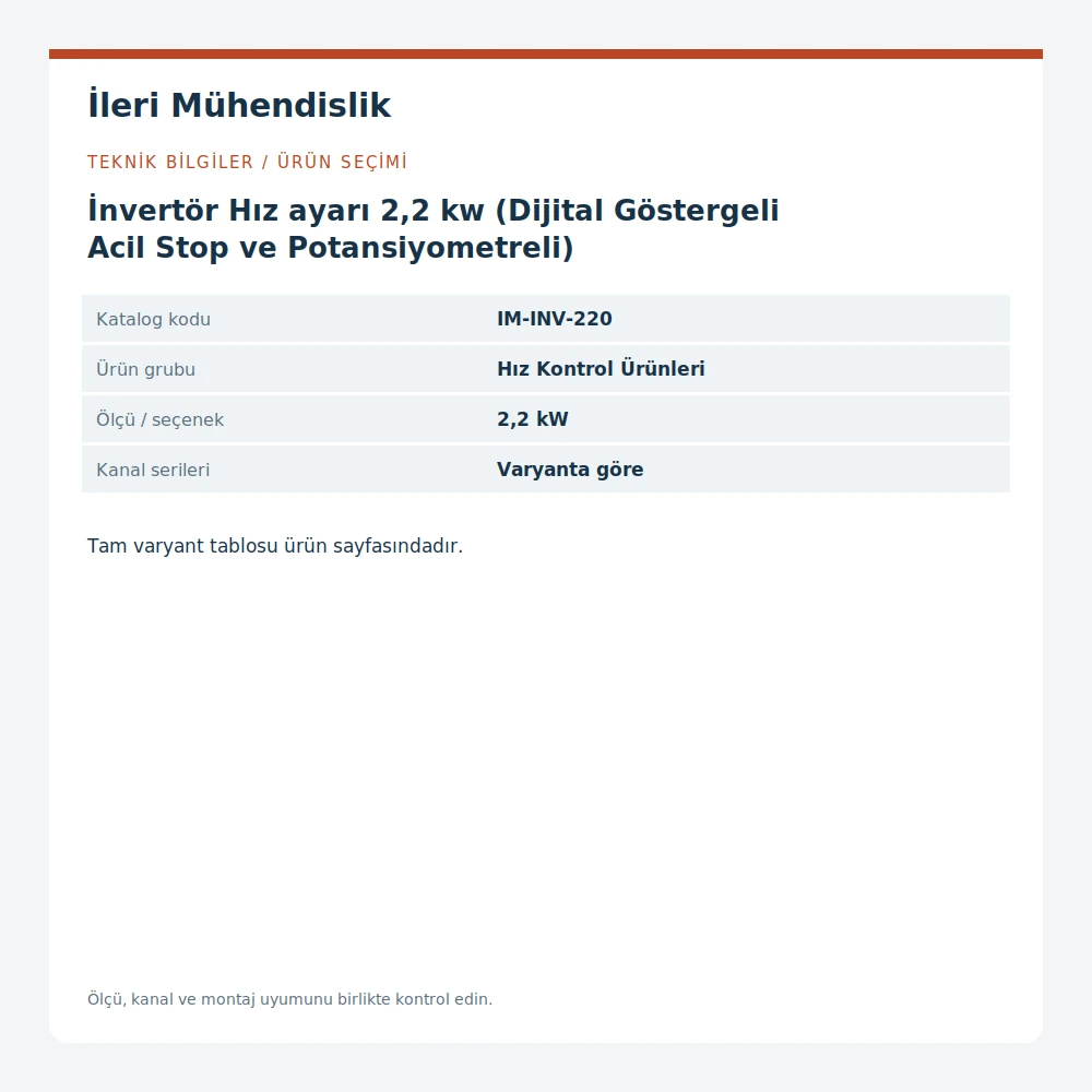
2.2 kW Converter Speed Control — Technical information
| Catalog Code | The IM-INV-220 |
Motor information for speed setting
When selecting the speed control product, the power value is not only considered. The engine's label information, power voltage, phase structure and working conditions should be shared together. The engines with the same power value may have different electrical properties. Therefore, the panel or driver layout is not accepted as compatible without matching the engine. The label photo is a useful entry in the preparation of the offer.
Operator and indicator
The digital indicator and potential meter are assessed to the operator to see or change the working settings. The tasks of the control elements and the speed settings range are determined according to the working scenario. The displayed value depends on the relevant equipment whether the engine is the turn, frequency or other size. It is unpredictable that each indicator function from the product head is the same.
Stop and machine communication
The task of the emergency stop element in the system must be dealt with the whole of the machine. The normal position of the carrier, the error position and the re-running are different conditions. If the signal is ready or full from other machines, the necessary entrances and outputs are indicated. The engine's change of direction, the frequency departure or the operation with a sensor may affect the control scope.
Placement and work environment
The control box is accessible to the operator, the cable route and maintenance access should be planned. The powder, water, temperature and vibration conditions are taken into account in the retention and selection of components. Connection and operation is done with the relevant equipment information by appropriate technical staff. The offer provides the correct preparation of the cover by describing the engine, power and desired working order.
When preparing a list of measurements
The indication of which surface or edge measurements are taken prevents the mix of similar parts. Cutting length, external measurement, channel openness and connection distance are different information. The unit used in the drawing must be the same in all lines. If the new one is to be taken instead of the existing piece, not only the total length, but also the details on the link side. Sharing product groups and parts in a regular list makes the range of the offer more clear.
Identify the variant correctly.
If there are more than one measurement or connection options within the product family, specify the line to be ordered. Similar names may be prepared for different channels, metric teeth or connection surface. The options in the technical table are not considered as parts that can be used in place each other. The photo and size of the profile section in the product to be added to a existing structure can also be added to the offer request.
Projects and Proposals
The list you will share with Advanced Engineering should include the product name, catalog code, size and piece. Listing the connectors of the same structure together reduces the likelihood of missing material. If you need a specific size, surface, processing or different settings, write it also. Photos help to understand the assembly; the measurable drawing allows the accurate assessment of the connectors. The supply scope is clarified in the supply phase.
Check before installation
The name and size of the delivered product must be compared to the prepared material list. Connector surfaces and the position of the piece in the project are checked. It should not be assumed that other products in the assembly samples are included in this pen. Profile, cottage, cottage or panel may also be required. The load and movement conditions in the application are not determined about the conformity of the whole structure without the knowledge of the load and movement conditions in the application.
Frequently Asked Questions
What information do you need when choosing this product?
The profile or assembly surface to be used in addition to the product name and size should be shared, the necessary pieces and working conditions. The variant table of products clearly indicates which option is required. If adaptation to a existing system is made, the measurable drawing or sample assessment will be made easier.
Are all the pieces included in the order?
In the assembly images, the profile, the link element or the assistant parts can be displayed together. The delivery range of this pen is described during the offer. It is recommended that you specify the shell, the cottage, the panel and other parts you need separately in your list.
How to check the conformity with the existing piece?
In addition to the outer appearance, the measurements of the channel, hole, tooth and assembly surface are compared. Combination of the product code alone may not be sufficient. The measurement, photo and if necessary the relevant variants are assessed through the sample.
Important products and offers
Sigma profile and linking elements catalogue You can check out other groups. Product control of speed You can compare the options in the same group from the section. with your size and list of items Ask for advanced engineering .