
Spot series
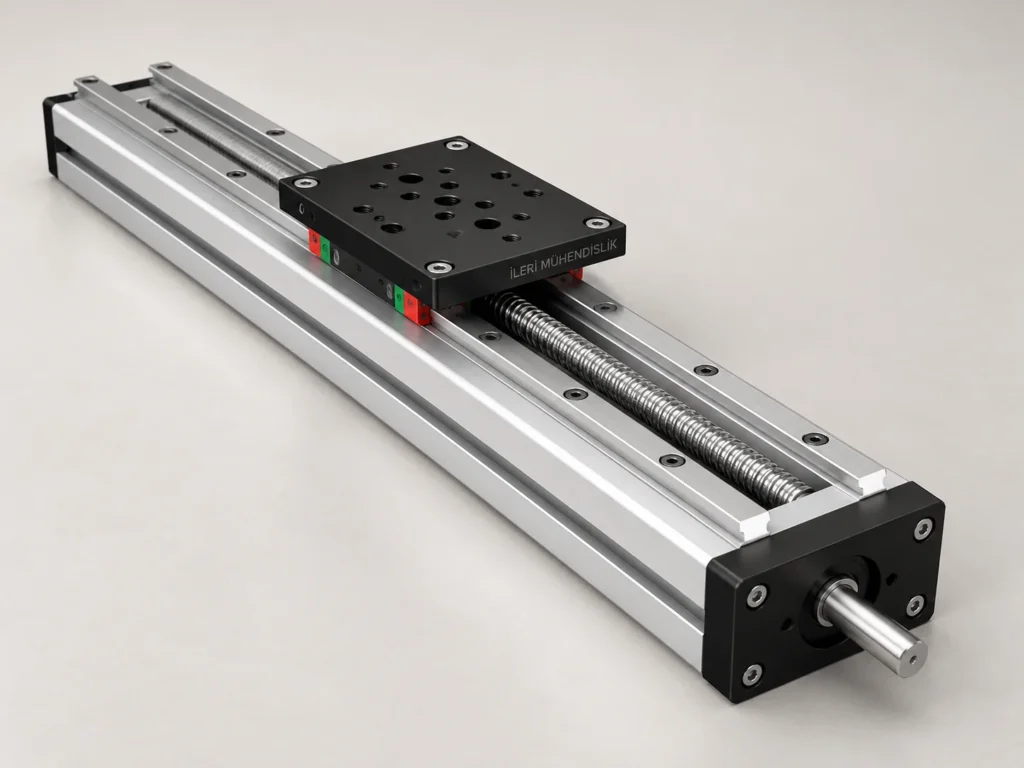
Compact slide module options with open work surface, which can be studied in small assembly volumes.
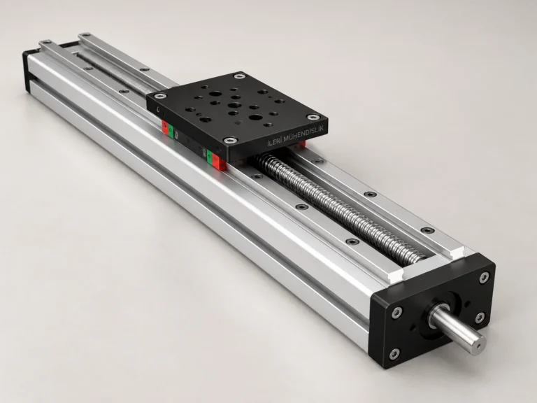
45x90 Spot Module
45x90 Spot Modül için ürün yapısı, teknik seçim bilgileri, montaj önerileri ve teklif hazırlığı. Strok, yük ve uygulama koşullarınızı İleri Mühendislik ile…
İncele →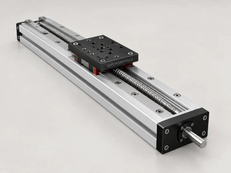
90x90 Spot Module
90x90 Spot Modül için ürün yapısı, teknik seçim bilgileri, montaj önerileri ve teklif hazırlığı. Strok, yük ve uygulama koşullarınızı İleri Mühendislik ile…
İncele →The mechanical structure of this group.
There are models options available in the small assembly areas of the spot group. The presence of a dust or dust source near the open work surface may change the need for maintenance and protection. The outward parts of the top plate must be checked throughout the movement. It should not be assumed that a model is suitable for every short stroke application, looking only to the body cut.
How to compare the product group?
The following product cards allow you to study the options that approach the same movement needs from different mechanical structures. The external size or serial name is not enough to make a choice alone. First describe the sizes of the part to be moved, the connection form and in which direction the force is applied during the movement. The moving mass includes the weight of the connection plate, the apparatus and the assistant elements as much as the piece. If there are multiple load conditions, it makes it more clear to determine the assessment to specify them separately.
Indicate the total and total length separately.
Net strok is the movement distance the car will use during the work. The total length of the product may be different due to the end connections and the carrier elements. Showing the end position with the beginning in a settlement draw is more explicit than just writing the total machine size. If end stopers, sensors or cable carrier are required, plan the area they cover. The support points of the main structure to be installed and the spaces assigned for service are assessed in the technical interview.
Connection and environmental conditions
The module or bedroom should be considered from which surface to the machine to be connected, along with the rigidity of the main shell. A properly selected product may not show the expected behavior on an inappropriate assembly surface. If there is a contact with the dust, dust, moisture and liquid, share this information. Protecting coverings and covers are considered according to the use environment. Access to maintenance and lubrication points should be placed in the design headquarters, as it will be necessary not only on the assembly day, but also during the later use of the machine.
Variant and delivery
There may be different plates, miles, rails or connectivity options within a product group. When examining technical tables, make sure the data belongs to which configuration. Don't move a value such as load capacity, speed or precision directly to different strok and assembly direction. Motor, driver, caplin, sensor, lock and special connectivity plates can also be added to the delivery range. Showing the necessary equipment in a single list makes it easier to evaluate the different parts of the offer together.
Preparation for technical meeting
Share the size of the upper table, the distance of the load from the center and the circle frequency are also effective in the selection. If you have a available system, you can add a measurable drawing or photo. If all the details in a new design are not yet clear, it is enough to explain the use scenario for the beginning. The final assembly measurements, the working conditions and the components to be delivered are clarified together with the technical assessment in the offer stage.
Selection of the model in the series
The values in the technical tables of the following models belong to the reference variant specified. The strok is determined in the final construction proposal stage according to the engine connection and the direction of operation.
Compare the application.
When comparing multiple models, examine them all through the same work scenario. It can be misleading to compare only the product names without the use of the same load, the same strok and the same assembly direction. If a problem occurs in a existing system, describe where the problem occurs. Observations such as difficulty at the beginning of the movement, noise at a specific position, release on the table or unconnection due to the narrow area may indicate different issues. These observations alone are not a failure diagnosis; it helps to understand where the technical examination will begin. Showing the directions and reference surfaces in a measurable drawing, it makes it easy to evaluate the product's conformity to your machine.
Setting a list of offers
Write the pieces and measurements for each model in a separate line. If there are multiple axes, separate them with clear names such as X, Y and Z; specify which axes carry the other. If different strokes from the same product are requested, don't combine them under one total size. Add to the list whether the connector elements, special plates and assistant equipment are included. If you need to match the existing piece, also mark the uncertain places of the size. Such a request list makes it easy to compare both the alternatives and to clarify the supply scope before the offer.
Share your size and working conditions
Let us evaluate the product selection together with the strok, load, assembly direction and quantity information.
WhatsApp üzerinden bilgi alın ↗