
Ø25 DKVM Serisi Modül
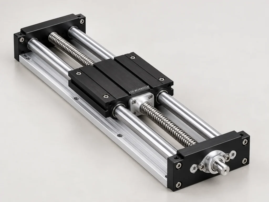
Ø25 DKVM Series Module is a product group selected by jointly assessing mechanical structure and working conditions for needs such as the horizontal automation axis.
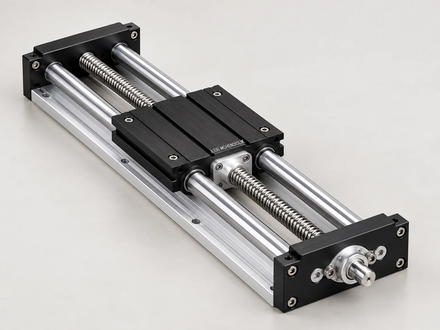
The mechanical carrier that needs a moment
Ø25 the car connection is important for a wide top table or a load fled from the center in the DKVM group. The extension of the guide diameter alone cannot meet the impact of the load in all directions. The connection plate, the bed range and the accuracy of the main shell should be checked in the same design.
Ø25 DKVM Series Module — technical selection information
| Group of Products | The DKVM series |
|---|---|
| The model definition | Ø25 DKVM Serisi Modül |
| Tahrik | The Mills of Miles |
| The length of the poster | 175 mm |
| The Miles | 25×05 |
| The Miles of Induction | Ø25 CF53 h7 |
| Maximum speed | 0,17 m/s |
| Net Strike | determined during the offer |
Table source defines a reference configuration in the catalogue. Visual is a representative work that tells the product group; the connection measurements and final components are verified through technical drawing.
Linear movement from the return movement
The wire wire in the drive turns the turn and the shell order into linear progress. The load direction is provided by the rail or guide mile order. The separation of these tasks explains why the choice of bed with the wire size is handled together. The engine can be directly connected or a different transmission order can be used; the engine, driver, caplin and connection flags can be separate delivery pen from the product body. The offer range therefore is not left only by the name of the module.
Net strok and total assembly length
The overall outer length of the module is different by the distance of the car progress. The end beds, body connections, caplin and motor section increase the total settlement. The two ends of the work range are assessed the approach parts and stop arrangement. In the technical drawing, the display of the starting and end positions of the load is more explicit than just the writing of the strok value. The area allocated for the moving cable and tubes should also be added to the assembly volume.
Speed, speed and moving load
The wire mill line defines the theoretical progress in a round. The actual speed requires the engine turn and the transfer rate if there is. The turn, the turn number and the total mass transferred are effective in the choice of the engine. The speed value in the reference table is not used as a general guarantee for all strok and loads. The life work length, support arrangement and the permitted turn are controlled. The positioning expectancy also assesses the driver and control system as much as mechanical spaces.
The Load Center and the Assembly Direction
The height of the apparatus on the car and distance from the axis affect the moment load. The work scenarios of a horizontal and vertical application are prepared separately. The energy cutting on the vertical load and the load holding arrangement are part of the design. The bilial wire arrangement is not accepted to be locked on its own. If more axis work together, the masses of the upper axis and connective plates are included in the load of the sub-transporter. The reactivity of the main wire also affects the assessment.
Environment, maintenance and offer
Add the dust, dust, liquid touch and temperature information to your technical request. The selection of the cover, cider or cider is considered according to the working environment; the appearance of the outside body is not a protection class declaration alone. The access to the flour and maintenance should be considered at the beginning of the installation. The demand must be the product group, the strok, the load, the speed target, the assembly direction and the engine preference together. The final assembly drawing and the supplied components are verified at the offer stage.
When describing the work
Note how many seconds a movement will be completed and how often it is repeated during the day. The presence in the starting and end positions is not the same as the continuous repetition of the movement throughout the day. Speak the empty and full movements in the circles where a piece is charged and dissolved separately. Remember that the moving load is not only made up of the weight of the piece; the top plate, the apparatus and the connector elements are also included in the account. Showing the access area to be separated for maintenance with the operator's work area in the drawing helps to evaluate the settlement problems that may be met after the installation. If the center of load changes during the strok to be used, also sign the negative position.
Frequently Asked Questions
Can the transportation capacity be determined by the model name?
The load direction, moment, struck, support distances and the chosen variant are assessed together.
What measures are required for the offer?
Note the net strok, total assembly area, moving mass, load center and connection surfaces. If you're choosing a existing piece instead, add the measurable drawing.
Other models in the DKVM series → · All linear movement systems
Technical reference is: Source catalogue information of the product family .
Share your size and working conditions
Let us evaluate the product selection together with the strok, load, assembly direction and quantity information.
WhatsApp üzerinden bilgi alın ↗