
90×180 Triger Kayışlı – Lineer Modül
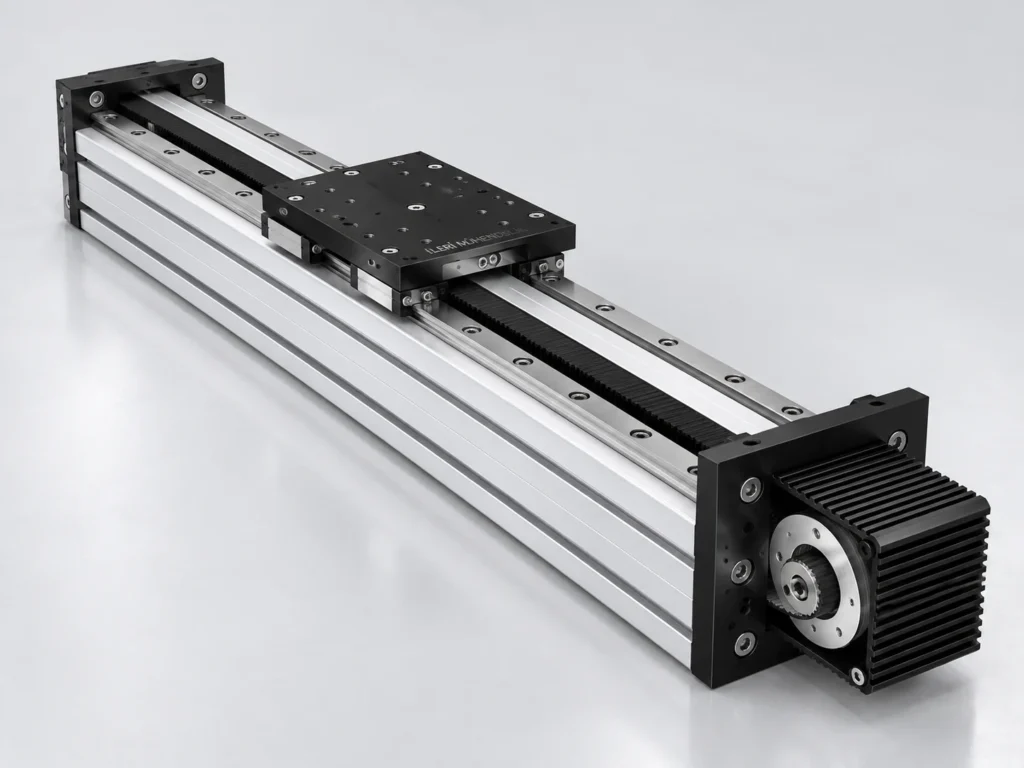
90×180 Triger Kayışlı – Lineer Modül, kayış tahrikli doğrusal hareket ihtiyacında kılavuzlama, yük ve montaj bilgileri birlikte değerlendirilerek seçilen bir modeldir.
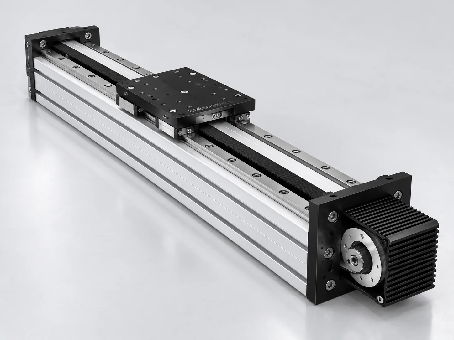
90×180 geniş raylı yapı
90×180 modelin geniş gövdesi, çift ray yerleşimi ve üst plaka bağlantısı birlikte değerlendirilir. Referans konfigürasyonda 205 mm plaka ve 8M 50 kayış tanımı bulunur. Geniş bir aparatın merkezden kaçık bağlanması, eksenin farklı yönlerinde moment oluşturabilir. Ana şasenin esnekliği de hareketli düzenin davranışında etkili olabilir.
Technical reference configuration
| The series | Linear series |
|---|---|
| Tahrik | Triger and the Crossing |
| The length of the poster | 205 mm |
| The Triger Chip | 8M 50 |
| Linear Ray | GHR 20 |
| Reference of source speed | 5 m/s |
| Net Strike | Approval is determined |
The technical table describes the variants specified in the source catalogue. Visual representation is a product work; the manufacturing and connection measurements are verified through technical drawing.
How to evaluate the trail?
The trigger thread transmits the movement between the shells to the linear carrier. This task is different from the guidance of the load. The rail or the coated bed carrier produces the shell movement while determining the direction of the carrier. The fact that a system is shelled alone does not explain the speed, capacity or positioning accuracy. The line definition, shell layout, moving mass and work circle should be evaluated together. The engine and driver may be separate delivery pen from the body; it is clearly indicated in the proposal that the cover of parts such as the connection flame and caplin is included.
The total length and length of the assembly
The length of the module from the outside to the outer with net strok is not the same measurement. The end drive group, the length of the car or plate and the approach parts affect the settlement. A measurable drawing that shows the starting and end position is more explicit than the total profile length is written only. Also specify the area allocated for moving cables, tubes and side connections. The area that needs to be left empty in the surrounding depending on the movement of the body or plate may vary. The desired strok is verified along with the final mechanical structure.
Load center, speed and circulation
The moving weight includes not only the moving pieces, but also the top table, the apparatus and the connective elements. The distance from the axis surface of this mass changes the moment effect. The speed target should also explain the acceleration, slowing and waiting times. The same carrier is not the same working condition to make continuous rotation throughout the day with a interim setting. The speed in the reference table is not a general guarantee for all loads and stakes. The drive, guidance and control system are selected together through the application.
Installation, maintenance and environmental conditions
The flatness and rigidity of the main structure to which the body is connected is important in the assessment of the movement. The assembly errors are not attempted to be fixed by just stretching the tape more. The back and guide settings should be done according to the technical method of the relevant product. If there is a dust, dust, moisture or liquid contact, add them to the demand. The appearance of a closed external body alone is not a statement of a specific protection class. The leaving the access area for the shifting, maintenance and, if necessary, shifting is part of the settlement.
What information is needed for the offer?
Share the model name, unit, net strok, load, working direction and approximately speed target together. It is useful to add the drawing that shows the connective holes of the upper plate and the center of the load. If there are more axes, specify which axes carry the other. In the renewal of a existing system, the line definition, the engine connection and external heights are also compared. If you need automatic signal exchange or sensor, write them into the delivery range. The final brand, variance and installation measurements are clarified in the proposal by technical conversation.
Planning the area of movement together.
The load and discharge positions of the product should be drawn together with the fixed machine parts around it. It is not enough that a device is fit only in the starting position; the external contour is controlled throughout the strok. The operator's work area, the direction where maintenance covers will be opened and the turn area of the cable carrier are also considered. If the use of the vertical axis is planned, the load holding when the energy is cut is also designed. It is unassured that the thread drive is a safe load lock itself. These details allow the mechanical product selection not to be separated from the whole machine.
Frequently Asked Questions
Can two models in the same section be used to replace each other?
The guide type, the strip, the plate and the assembly layout are not accepted equal without verification.
Can the image be taken from the mount?
There is a need for the technical drawing for the hole locations, stroke and stimulus connection.
Other models in the Linear Series · The Triger Systems
Technical reference is: Source catalogue information of the product family .
Share your Strok and Application Information
Let’s evaluate the thread, guidance, assembly and drive range together.
WhatsApp üzerinden bilgi alın ↗